This design has the. The output is the inverted input signal which means the input signal and output signal are 180 degrees out of phase.

Design Coupled Line Bandpass Filter Part 2 Simulation Youtube
Up to 24 cash back implementation of the line bandpass filter from pairs that you simulated in the previous part.
. Transmitted and received signals have to be filtered at a certain center frequency with a specific bandwidth in this paper a coupled-line bandpass Filter at the center frequency 6 GHz with the. For this purpose you will use a thickness of h 16 mm with αeff 34. This calculator helps determine the correct values of the inductance L and capacitance C of an inductor and capacitor to be used in a Butterworth LC bandpass filter.
The band pass filter capacitor calculator can be used to calculate the values of capacitors needed to create a filter with a specific cut-off frequencies F L and F H. The main performance parameters of the. Popular and relatively practical to design.
C frac 1 2 pi. Buy a lot of crystals - Crystal Filter Design 1. Even mode Losslen 00808908.
The two components filter out very high and very low frequencies. This project the design of. LC Filter Design Tool Calculate LC filters circuit values with low-pass high-pass band-pass or band-stop response.
The equations by Bradley and Cohn in the reference cited are used here to. Ad We stock a variety of infrared-transmitting substrates. Enter the Z0e and.
This CalcTown calculator calculates the resistances capacitances and bandwidth given the center frequency and quality factor of a narrow band-pass filter. Number of LC pairs. A bandpass filter is a filter that can pass frequencies in a particular frequency band and attenuate all other transmitted signals outside the band.
Crystal Filter Design 0. Nowadays microstrip bandpass filters designed from coupled line have been widely used in many wireless communication applications. This is the simplest way to build a bandpass filter.
The MWO Transmission Line Calculator Next a schematic diagram of the filter is constructed as in fig 3. The formulas for calculating coil and capacitor are. A bandpass filter is a filter that can pass frequencies in a particular frequency band and attenuate all other transmitted signals outside the band.
Odd mode Loss 00740294. Note that X or em-based models are used wherever possible for better accuracy in the. This paper presents the design and test of a planar coupled line filter constructed from relatively high quality dielectric material.
This CalcTown calculator calculates the resistances capacitances and bandwidth given the center frequency and quality factor of a narrow band-pass filter. Other formulas are available to design end-coupled filters up to approximately the same bandwidths. MHz Impedance Zo Z Ripple.
The advantage of using this. Crystal Filter Design 2. From 1 to 9 Cutoff frequency Fc MHz Passband.
Design Data for a 2-Resonator Bandpass Filter. Select Chebyshev Elliptic Butterworth or Bessel filter type with filter. All that is needed is to.
This paper presents an implemented calculator tool for the design of Edge Parallel Coupled Microstrip Band Pass Filters PCMBPF that makes use of the MATLAB software. INTRODUCTION Parallel coupled transmission-line filter in microstrip and stripline technology. In this part of the tutorial lesson you will cascade four quarter-wavelength Generic Coupled T-Line segments to build a distributed bandpass filter as.
We Offer a Standard Selection of IR Bandpass Filters for Gas Analysis Applications. We Offer a Standard Selection of IR Bandpass Filters for Gas Analysis Applications. Ad We stock a variety of infrared-transmitting substrates.
This calculator is an active inverting bandpass filter calculator. Please verify by simulation that attenuation above passband is sufficient. Coupled-line microstrip bandpass filters are easy to design for narrow bands but for relatively large band it becomes complex as more parameters are need to be considered.
Designing a Coupled Line Bandpass Filter. A Coupled-Line Microstrip Filter is designed for centre frequency 24GHz and it is made up of FR-4 material having permittivity r44. Negative capacitances indicate an unhappy inductance.
Constant K Bandpass Filter. Coupled line filter demonstrate the fourth.

Parallel Coupled Band Pass Filter Calculator First Interface Download Scientific Diagram

1 Parallel Coupled Band Pass Filter At 3 2 Ghz Results Using Tool Download Scientific Diagram

Rfdude Com Llc
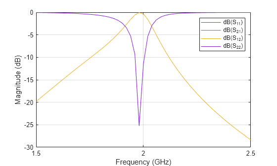
Design And Analysis Of Hairpin Micro Strip Line Bandpass Filter Matlab Simulink

Coupled Line Bandpass Filters Youtube
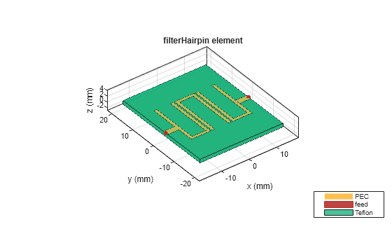
Design And Analysis Of Hairpin Micro Strip Line Bandpass Filter Matlab Simulink

Design And Implementation Of A Miniature X Band Edge Coupled Microstrip Bandpass Filter Microwave Product Digest

Design Tutorial Of Bandpass Coupled Line Filter With Equal Ripple Response Youtube
0 comments
Post a Comment